- 您現在的位置:買賣IC網 > PDF目錄382287 > MAX828 (Maxim Integrated Products, Inc.) Parallel-Load 8-Bit Shift Registers 16-CFP -55 to 125 PDF資料下載
參數資料
| 型號: | MAX828 |
| 廠商: | Maxim Integrated Products, Inc. |
| 英文描述: | Parallel-Load 8-Bit Shift Registers 16-CFP -55 to 125 |
| 中文描述: | 開關電容電壓反相器 |
| 文件頁數: | 16/18頁 |
| 文件大?。?/td> | 158K |
| 代理商: | MAX828 |
MAX828, MAX829
http://onsemi.com
16
+
5
4
2
3
1
OSC
MAX828: Capacitors = 10 F
MAX829: Capacitors = 3.3 F
+
+
V
in
+
+
+V
out
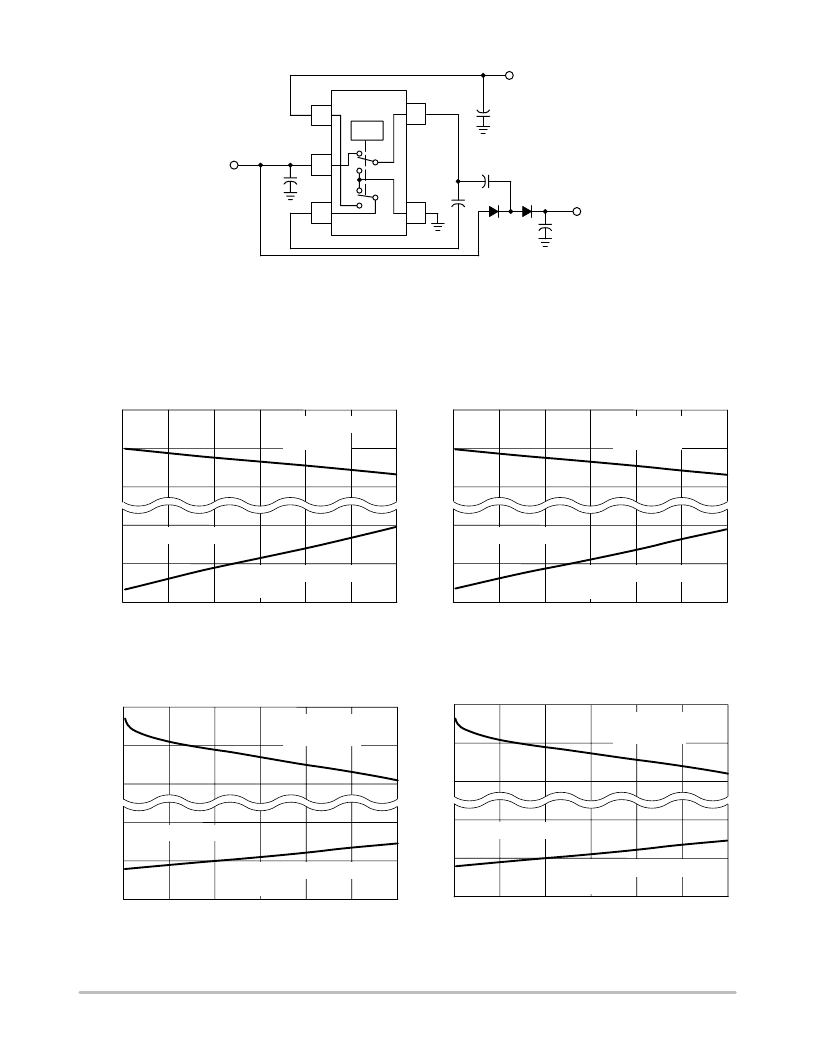
Figure 51. A Positive Doubler, with a Negative Inverter
V
out
All of the previously shown converter circuits have only single outputs. Applications requiring multiple outputs can be
constructed by incorporating combinations of the former circuits. The converter shown above combines Figures 24 and 36 to form
a negative output inverter with a positive output doubler. Different combinations of load regulation are shown below. In
Figures 52 and 53 the positive doubler has a constant I
out
= 15 mA while the negative inverter has the variable load. In Figures 54
and 55 the negative inverter has the constant I
out
= 15 mA and the positive doubler has the variable load.
I
out
, NEGATIVE INVERTER OUTPUT CURRENT (mA)
Figure 52. Negative Inverter Load Regulation,
Output Voltage vs. Output Current, MAX828
V
o
,
0
30
20
10
5.0
9.0
4.5
9.5
8.5
4.0
I
out
, NEGATIVE INVERTER OUTPUT CURRENT (mA)
Figure 53. Negative Inverter Load Regulation,
Output Voltage vs. Output Current, MAX829
V
o
,
Negative Inverter R
out
= 28
T
A
= 25
°
C
0
30
20
10
5.0
9.0
4.5
9.5
8.5
4.0
Positive Doubler
I
out
= 15 mA
Positive Doubler
I
out
= 15 mA
Negative Inverter
Negative Inverter
Negative Inverter R
out
= 28.8
T
A
= 25
°
C
I
out
, POSITIVE DOUBLER OUTPUT CURRENT (mA)
V
o
,
Figure 54. Positive Doubler Load Regulation,
Output Voltage vs. Output Current, MAX828
Positive Doubler
R
out
= 21.4
I
out
, POSITIVE DOUBLER OUTPUT CURRENT (mA)
V
o
,
Figure 55. Positive Doubler Load Regulation,
Output Voltage vs. Output Current, MAX829
0
30
20
10
5.0
9.0
4.5
9.5
8.5
4.0
0
30
20
10
5.0
9.0
4.5
9.5
8.5
4.0
T
A
= 25
°
C
Positive Doubler
R
out
= 20
Negative Inverter
Negative Inverter
T
A
= 25
°
C
Negative Inverter I
out
= 15 mA
Negative Inverter I
out
= 15 mA
相關PDF資料 |
PDF描述 |
|---|---|
| MAX829EUK | Parallel-Load 8-Bit Shift Registers 20-LCCC -55 to 125 |
| MAX828EUK-T | IC-SM-VOLTAGE INVERTER |
| MAX829EUK-T | IC-SMD-SWT CAPACITOR INVERTER |
| MAX828 | Parallel-Load 8-Bit Shift Registers 16-CDIP -55 to 125 |
| MAX829 | Switched Capacitor Voltage Converter |
相關代理商/技術參數 |
參數描述 |
|---|---|
| MAX828/D | 制造商:MAXIM 制造商全稱:Maxim Integrated Products 功能描述:Switched Capacitor Voltage Converters |
| MAX828_05 | 制造商:ONSEMI 制造商全稱:ON Semiconductor 功能描述:Switched Capacitor Voltage Converter |
| MAX828C/D | 制造商:MAXIM 制造商全稱:Maxim Integrated Products 功能描述:Switched-Capacitor Voltage Inverters |
| MAX828C/D DIE | 制造商:Maxim Integrated Products 功能描述: |
| MAX828EPA | 制造商:Rochester Electronics LLC 功能描述: 制造商:Maxim Integrated Products 功能描述: |
發布緊急采購,3分鐘左右您將得到回復。